


Specifications
- Maximum terminal current: 4A
- On-state gate voltage: 1.4V
- Gate trigger current: 10mA
- Max terminal voltage: 600 V
- Holding current: 2.2mA
- Latching current: 4mA
- Package includes: 5 pieces
Available in Pack Of:
SKU: 694KB
MRP Rs. 67.85
Rs.
59.00
(Incl. Tax)
Rs.
50
(+18.00% GST extra)
Rs. 50 / pack of 5 = Rs. 10.00 per piece
Buy to Get ₹0 off!
₹0 Special Discount Applied
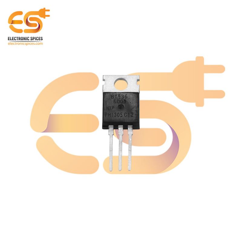
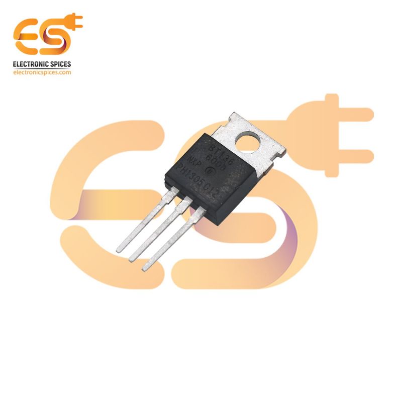
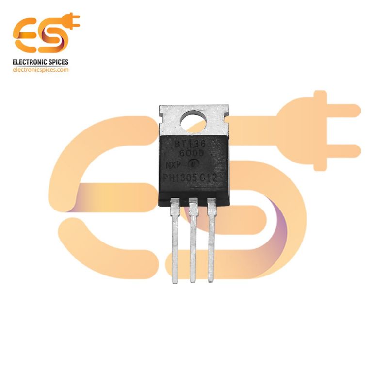
BT136-600D Transistor TRIAC 600V 4A pack of 5pcs
The BT136-600D Transistor is TRIAC with 4A maximum terminal current. The gate threshold voltage of the BT136 is also very less so can be driven by digital circuits. Since TRIACs are bi-directional switching devices they are commonly used for switching AC applications. So if you looking to switch control (dim, speed control) an AC load that consumes less than 6A with a digital device like a microcontroller or microprocessor then BT136 might be the right for you.
Package includes
This is the pack of 5 pieces of BT136-600D Transistor TRIAC 600V 4A
Applications
- AC Light dimmers
- Strode lights
- AC motor speed control
- Noise coupling circuits
- Controlling AC loads using MCU/MPU
- Ac/DC Power control
Tips
Since TRIACS deal with AC voltages, the circuit involving them has to be designed properly to avoid problems some tips are shared below
- All TRIAC circuits suffer from an effect called Rate Effect. This occurs when the TRIAC is switching frequently and a sudden high voltage occurs at either main terminal of the TRIAC and damages the TRIAC itself. It can be avoided by using a snubber circuit.
- Similarly, there is another effect called the backlash effect. This occurs due to the capacitance that gets accumulated between the two terminals of the MT1 and MT2 of the TRIAC. Due to this, the TRIAC will not turn on even if the gate voltage is applied. This problem can be solved by providing resistance in series for the capacitance to discharge.
- When controlling the output AC voltage for dimmer or speed control applications a Zero crossing method is always recommended to be used.
- In switching circuits the TRIAC is easily subjected to harmonics and EMI interference hence should be isolated from other digital electronics.
- There is a chance of backward current when the TRIAC is switching inductive loads, so an alternate discharge path has to be provided for the load to drain the inrush current.
Related Tags:
bt136, bt136 transistor, triac circuit, bt136 circuit, a step of transformer, Electrical step down, mini step down converter, 600V 4A transistor
bt136, bt136 transistor, triac circuit, bt136 circuit, a step of transformer, Electrical step down, mini step down converter, 600V 4A transistor
Social Links:
Country Of Origin:
China
Manufactured / Packed / Imported by:
ESRDNS PRIVATE LIMITED
Jaitpur Extn. Part-1, E-1/103, Badarpur,
New Delhi, South Delhi, Delhi, 110044
Hi, Try Me
Find Some Matches!
Find Some Matches!

Curating For You...
AI-Powered Suggestions
Recently Viewed Products

Related products